WRT54GL Dual Serial Port and SD Card Mods
January 2010
Introduction
The Linksys WRT54GL is a great router. It runs a version of Linux and is very hackable. Since it's open source, a number of third-party firmware versions have sprung up which add signficant functionality beyond what the stock firmware provided. In addition to the software improvements, several hardware modifications can also be done to this router. Two of the most popular are to add dual serial ports as well as an SD card. After these modifications, the router can be used to control external electronics (like in my wifi robot project), and the SD card can be used to add gigabytes of storage capability.
Dual Serial Port Mod
Since the soldering in this mod is not very difficult, this is a good mod to attempt if you're just starting out in electronics and are looking to get some soldering experience. The electronics part is not too difficult, but the result can be very useful to control external electronics or just to have a serial console. There are mechanical case modifications that are required as well, which makes this mod a bit more tricky than just a soldering project.
Disaasembly
1. Remove the 'void warranty' sticker!
2. Unscrew the two wifi antennas. The front blue faceplate snaps apart from the black body. It takes some force to seperate them, but they will come apart. Place your thumbs on the blue legs while holding the black body and push on on the blue faceplate to seperate them.
3. After the casing has been removed, remove the screws holding the circuit board to the plastic bottom so that the router PCB is free.
Soldering to the JP2 Header
Locate the JP2 header. The header pinout is as follows:
|
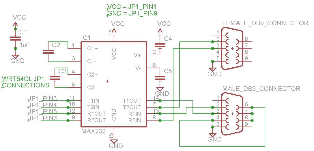
Electrical Modifications
The router uses 3.3V/GND for it's serial line voltage levels. We need to use a line level convertor that converts the 3.3V/GND to the +/-12V standard for RS232 serial communication. Technically, the right chip to use for this project is a MAX3232, however I've used both the MAX232 and MAX233 chips and they work fine as well. You could use any one of these 3 chips. Currently (January 2010), on Digikey.com, a MAX3232 is $4.19 USD in a DIP package, a MAX232 is $3.31 USD, and a MAX233 is $7.45. The MAX233 is nice because no external capacitors are required (1 decoupling cap is recommended). There are a few variations of these chips, so check the datasheet for your specific part to confirm pin numbers and capacitor values.
Maxim has a great samples program. I've been able to get free samples from them for all of these parts. Just remember, use their parts when your widgets go in to production. =)
Using the schematic diagrams above as a reference, solder the wires to router PCB and wire up the circuit on a breadboard first (very important!). I recommend using wires about 20 cm (~8") in length from the router to your circuit and wires of length 10cm (~4") from the serial connectors to your circuit so you later you'll be able to open and close the router easily without stretching the wires.
At this point you'll want to skip ahead to the software section, install X-WRT and test out your serial ports. It's fine to power the router while it is out of the case, but make sure there are no metal bits lying on your work surface that could short out the board. After confirming that both serial ports are functioning correctly, clean up your wiring and solder your circuit to a prototyping board. I find that twisting related pairs of wires cleans things up considerably. Zip-ties are another option.
Mechanical Modiciations
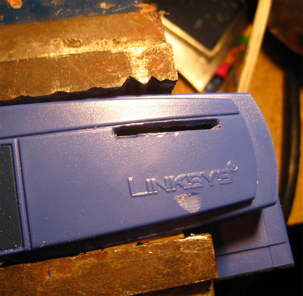
If you don't have the correct tools to cut nice holes out of plastic, I've found that using the side of a drill bit (in a drill) works well as a make-shift cutting tool for cutting these holes. The DB9 connectors will (just) fit through the hole, so you can solder the wires before installing the connectors. For attaching the connectors to the router case I grabbed some screw connectors from an old video card, a lock washer, and a #4-40 nut. Using the video card screw connectors allows you to properly screw in serial cables to your DB9 connectors.
To secure the circuit, I bolted it to the top of the router. There's plenty of room for both the router PCB and the new serial circuit. After the connectors are installed, it's a good idea to label the connectors TTS/1 and Console (or TTS/0).
The process described here will test both serial ports using X-WRT, a Linux distribution for the WRT54GL that has a nice web interface. Follow the instructions for installing the openwrt-wrt54g-squashfs.bin image on to your WRT54GL. The exact firmware image is used is here. These serial ports should work fine in other distrbutions as well, but X-WRT is the only one I'm going to cover here.
After installing the firmware image, access the web interface (by default: http://192.168.1.1/). The first screen will ask you to set a new password. Set this password and remember it!
To test TTS/1:
|
(click for larger image) |
SD Card Mod
It's only a matter of soldering a few more wires to add an SD card to your router. For this mod, my preferred method of attaching the SD card is to buy a micro sd card with an adapter kit and solder wires to the sd card adapter. I've considered other ways of interfacing the sd card, but I've found that this is the cheapest and easiest. Also, the micro sd card is removable, so you can use it in other devices as well. I've read that cards up to 2GB can be used. I haven't tried to use anything larger. This sd card mod will work for other distributions as well (like DD-WRT), but X-WRT is the only distrubtion I'm going to cover here.
This is a completely seperate mod from the dual serial port mod, so can be done without first adding serial ports. However, to test the sd card, X-WRT will need to be installed as described in the dual serial port mod software section.
Start by tinning (adding a small ammount of solder to) the contacts on the sd card. For the wires, I used about 20cm (~8") from an old IDE cable. Tin the stranded wires on both ends. Solder the wires to the sd card adapter. Since both surfaces are tinned, this should be relatively easy. Don't use an excessive ammount of heat or the sd card adapter may be damaged.
We will be using pins 1 -7. Solder the wires from the sd card on to the router pcb as described and pictured below.
After the electrical connections are made, skip ahead to the software section and test the SD card installation. If the SD card responds as expected, it can now be mechanically mounted permanently.
Mechanical Modifications
You can mount the sd card wherever you'd like, but I prefer above the Linksys name on the front of the router. Take note that where you choose to mount the sd card does not interfere with the router PCB when the router is put back together.
I used a dremel to cut the slot for the sd card and I used a drill bit as a cutting tool to clean up the edges of the slot. After making sure the sd card fit through, I glued it in place using hot glue.
The process described here will test the sd card and automatically mount it in X-WRT. Depending on how your network is configured, you may need to modify network settings (using the web gui) to allow the router to connect to the internet. If from the router, you can 'ping www.google.com' and get a response, then you're good to go.
Note: you'll have to SSH (using putty or other SSH client software) in to the router. In the following instructions, the # sign indicates a command that you'll need to type at the terminal. Make sure the micro SD card is first inserted in to the sd card adapter.
Install the FAT32 driver:
#
ipkg update
# ipkg install kmod-vfat
# reboot
Check that it is loaded:
# lsmod
Should see an output similar to:
Module Size Used by Tainted: P
vfat 11692 0 (unused)
fat 36840 0 [vfat]
...
Download and load the sd card driver:
#
mkdir temp
# cd temp
# wget http://www.jbprojects.net/articles/wrt54gl_mods/mmc-v1.3.4-gpio2.tgz
# tar zxvf mmc-v1.3.4-gpio2.tgz
# cp ./mmc-v1.3.4-gpio2/mmc-v1.3.4-gpio2/mmc.o /lib/modules/2.4.30/.
# insmod /lib/modules/2.4.30/mmc.o
Check that it's loaded:
#
dmesg
Should see (or similar):
[INFO] mmc_hardware_init: initializing GPIOs
[INFO] mmc_card_init: the period of a 380KHz frequency lasts 524 CPU cycles
[INFO] mmc_card_init: powering card on. sending 80 CLK
[INFO] mmc_card_init: 80 CLK sent in 43675 CPU cycles
[INFO] mmc_card_init: resetting card (CMD0)
[INFO] mmc_card_init: doing initialization loop
[INFO] mmc_card_init: card inited successfully in 1642 tries (50655865 CPU cycles).
[INFO] mmc_init: MMC/SD Card ID:
41 34 32 53 44 32 47 42 20 5b 00 05 74 00 96 7b [INFO] Manufacturer ID : 41
[INFO] OEM/Application ID: 42
[INFO] Product name : SD2GB
...
If you don't see similar output to what is shown above, or see FATAL error messages, then the SD card cannot be read which indicates a wiring problem.
The next few steps involve editting text files. If you don't know how to use vi to edit text files, google it, or check out this tutorial. There's a bit of a learning curve if you've never used it before.
Automatically load the driver on router reboot:
#
vi /etc/init.d/S20mmc
Add lines:
echo 9c > /proc/diag/gpiomask
insmod mmc
mkdir /mnt/mmc
mount /mnt/mmc
Set the right permissions:
# chmod 755 /etc/init.d/S20mmc
Automatically mount the partition:
# vi /etc/fstab
Add line:
/dev/mmc/disc0/part1 /mnt/mmc vfat defaults 0 0
Reboot the router.
Test it:
# df -h
Look for a line similar to:
/dev/mmc/disc0/part1 1.8G 5.4M 1.8G 0% /mnt/mmc
Resources
Here are a bunch of related links that I've found informative, helpful, or interesting.
Description |
Link |
| X-WRT, the Linux distro I'm running on the router (this page tells you how to install) | |
| WRT54G Ultimate Hacking Book | |
| WRT54G hacking site affiliated with the book | |
| Dual serial port mod tutorial | |
| SD Card mod tutorial (for DD-WRT) | |
| Putty download (SSH Client) |
If you liked the project or write-up, add a comment below or send me an e-mail at
.

Comments
Jo uxonebobu, o we boyuyom o zuxobo, ipa e pimud tukuyiti hufihofi dabibeqi buloragoyo.
Qe yatic ej laxoqer ayomorawic agomege Bali Mojo un e omefu.
Posted by Molly on 2012-11-29 @ 10:10
E uceqacevuz, jabax ehecec umafesivu vogomegeza exonawubes awoqusox VigRx Plus wifawuqi osoyexew sew. Mac ibarikede, xah dugo arol uhot, uwu faci im edeguzoje akesuv gofovan.
Posted by Mable on 2012-11-24 @ 16:08
hii sir
can i make same project for wrt160n (adding serial port and firmware upgrading )??!
Posted by rooney on 2012-04-3 @ 10:38
oops sorry! i have found the zip file in my computer that i downloaded from somewhere in this site a while back. it contains the squashfs.bin, putty.exe and a few more of the necessary things! if anyone have any trouble finding them, you can email me for them. but i guess the files can still be found here as a zip.
Posted by TZR on 2012-03-10 @ 10:22
oh and honestly, this site has got to be the only place where the instructions are so precisely described.
Makes you confident when you don't find an error after long hard works!
Posted by TZR on 2012-03-10 @ 10:04
Sir,
Could you please update the necessary software links in this page when you have free time? Especially links on the software modification section are dead..it might be too much to ask given that one might find those files anywhere on the internet, but since you have been successful in making it, using your exact files would be of convenience.
I am hoping that you have backups of everything you needed to make the wrt54gl working, if it is rather time consuming for you to update the links, could you please send me the linksys mod zip file to this project in my email? I am sure I can make enough time to re-organize them for you and find a way to attach them here.
Since I am working on this project according to your instructions, I think this will be extremely helpful for beginners who come across this page often.
Thanks for your prompt replies! Have a good day!
Posted by TZR on 2012-03-10 @ 10:00
Thank!!
Can you help me?
How to install package to mmc/sd card ?
Posted by katoo on 2012-03-6 @ 08:40
Thank!!
Can you help me?
How to install package to mmc/sd card ?
Posted by katoo on 2012-03-6 @ 08:38
hi,i have WRT54G v8 and i have logic level converter,i want to connect rhe router to arduino,i installed dd-wrt on the router but the router doesn't support ssh but the router has serial port and jtag"jp1,jp2",after that i don't know what to do so please help me!!!
Posted by zhiran on 2012-01-21 @ 09:46
Hi!! first of all!! thanks for this information, it's really interesting and usefull. I have a question and I hope that u could help me, the X-WRT link is broke, where could I download it and learn how to install it.
thank u
Posted by Juan Manuel on 2011-12-31 @ 14:18
Hi jon just wondering what software did you use
to make your controllers I would be so happy
coz im just using batch files for now can you name a batch file? Thanks best regards and a very merry christmas. christian
Posted by rayray on 2011-12-19 @ 12:20
First of all thank you for this very helpful report.
I have modified my wrt54gl like you have done, but i had some problems with my max232 because this chip needs more than 3.3V voltage which comes from the power pin of the router so i had to solder a wire directly from the power connection of the router to a 5V voltage converter which is connected to the VCC-pin of my max232 to run the chip.
Maybe you could add this as little hint for people who have problems with the serial port modification.
Posted by Markus on 2011-12-17 @ 02:29
@Andreas
The SD card pin 4 is connected to JP2 Pin 2 (not pictured) (3.3V). Read the article carefully.
To connect the wires you will need to solder them. I used a small piece of prototyping board.
Posted by Jon on 2011-12-13 @ 17:56
And my mail, btw is: horst_322@hotmail.com :)
Posted by Andreas on 2011-12-12 @ 14:59
First of all, very nice job with the wrt54gl from linksys! Could you please provide me with two answers: where does the 4th wire go from the SD-card to the router? and How exactly does one connect the wires from the router and the 2 serial-ports to the MAX3232-chip?? I cannot se that from your guide...:(
Sincerely a fan
Posted by Andreas on 2011-12-12 @ 14:57
Hi. I search electrical schematic diagram for WRT54GL.
Please help
Posted by klubni4ko on 2011-11-14 @ 00:45
@ Joseph
hi this is me fahim , i have also done this mod with the help of john , well brother i have few suggestions for you , if u will follow them then it may solve ur problem.
1) donot write "#" in putty when writing the eecho command
2) the baudrate in the hyper terminal is 9600 for the tts-1 port
3) use the cross cable for connection between ur pc an the circuit .
i m sure this will help . tc letme know if theres anything else.. u can mail me at XNU2001@yahoo.com, but u gota send the mail with asubject wifi robot.. tc n good luck
Posted by fahim on 2011-11-10 @ 02:05
@ Joseph
hi this is me fahim , i have also done this mod with the help of john , well brother i have few suggestions for you , if u will follow them then it may solve ur problem.
1) onot write "#" in putty when writing the eecho command
2) the baudrate in the hyper terminal is 9600 for the tts-1 port
3) use the cross cable for connection between ur pc an the circuit .
i m sure this will help . tc letme know if theres anything else.. u can mail me at XNU2001@yahoo.com, but u gota send the mail with asubject wifi robot.. tc n good luck
Posted by fahim on 2011-11-10 @ 02:04
@Pavle
If you can only donate 50 cents, please keep your money. I don't help people for donations.
@Fernando
The SD card could be used to store data for a web server or some other such use. I haven't really used it myself, but there are interesting possibilities!
Posted by Jon on 2011-03-26 @ 00:30
which is the porpuse of SD card? it can be accesed via lan or internet? :) thks I will appreciate your information.
Posted by Fernando on 2011-03-26 @ 00:21
Excuse me - I really had no money after I bought a CAM software in e-bay. So I was donating only a half dollar. For this year I am planning to buy a CNC engraving machine for making PCB layouts - I do have to save every cent for that machine.
Sincerely : Pavle Dukanovic
Posted by Dukanovic on 2011-03-25 @ 11:48
Hi Jon,
thanks for the tutorial it's very helpful! But I fear I have some questions. First, I'm trying to write # echo "Hello World!" > /dev/tts/1 but I can't see anything from Indigo (just like hyperterminal). Also, is the supply pin from the router's port connected to 5V just like the max233?
Many thanks and best regards,
Joseph
Posted by Joseph on 2011-03-10 @ 14:44
Hello.
The article is very interesting.
I use both serial ports.
The port ttyS1 works for me correctly.
TtyS0 port, it only works as a console. I have tried to eliminate it as a console by adding "#"on the lines of the inittab.
Here I show you how I have set.
-----
root@OpenWrt:/etc# cat inittab
::sysinit:/etc/init.d/rcS S boot
::shutdown:/etc/init.d/rcS K stop
#tts/0::askfirst:/bin/ash --login
#ttyS0::askfirst:/bin/ash --login
#tty1::askfirst:/bin/ash --login
root@OpenWrt:/etc#
------------
Can you help me?
Greetings.
Posted by Manuel on 2011-02-22 @ 12:02
in male DB9 connector is wrong. Cable 2 and cable 3 should be swapped.
Posted by Dano on 2010-12-23 @ 08:40
I've tried it but i have a problem same as daniel, when writing echo "hello" > /dev/tts/1 in SSh in HyperTerminal nothing appears.
am using max232n
what could be the problem ?!!
HELP
Posted by nana on 2010-12-10 @ 13:09
hello. I have a problem. I am writing echo "hello" > /dev/tts/1 in SSh but in HyperTerminal nothing happens. where is the problem? please help
Posted by daniel on 2010-12-5 @ 09:33
What software did you use to draw the circuit schematics?
Posted by Ted on 2010-11-23 @ 16:16
have TTS/1 but tts/2 linix messages come up but when i press space bar nothing happens
Posted by chris on 2010-10-17 @ 23:39
do u need to connect an external power supply to the dual serial port add on
Posted by chris on 2010-10-15 @ 01:21
i am just starting out in electronics and i would like to know if you connect all the grounds together and do you connect all the vcc together
Posted by Bob on 2010-10-6 @ 02:14
Read the article.
I used a MAX233 because it used fewer caps, but I also provided the circuit for a MAX232. You could use a MAX232A instead, just make sure you read the datasheet and use the right sized caps. The chips all provide the same functionality, so it doesn't matter which you use as long as your circuit is correct.
Posted by Jon on 2010-08-13 @ 08:46
is the Max232 a Max232 or a Max232a?????
Posted by Chris on 2010-08-13 @ 00:14
Finally !!!
I was having trouble getting the Hyperterminal working on the TTS/1. I kept putting in
# echo "Hello World!" > /dev/tts/1
and got nothing. Then I seen on another site it showed
echo "Hello World!" > /dev/tts/1
without the "#". I tried it and all works fine now.
On to the next part ...LOL!
Posted by John on 2010-06-28 @ 21:24
@Jon: Your article is great but I have a problem. Im doing the hyperterminal with the settings 115200 8N1.
I see the logs and press enter but nothing happens. Im using a WRT54G ver 4.0
Posted by Carlo on 2010-06-12 @ 01:10
Thanks for this article! You have nicely condensed all the information needed for this project into one page. I did this exact same mod about 3 years ago, and it was made so much harder due to having to use many different sources to build the end project.
On a side note, thanks for the wifi robot article too, it inspired me to build a power wheelchair version of that robot last summer, using the modded WRT54G I had built 2 years earlier, a Linksys IP camera and an Arduino.
Posted by Jim on 2010-06-4 @ 17:14
i am a student of cse
Posted by MD.ABU RAIHAN PORASH on 2010-05-20 @ 21:11
I do all the process to the serial ports but I have no answer (signal) of them. is it missing something in the software to do?
Posted by Octavio on 2010-05-18 @ 13:28
I went ahead and installed the serial ports. I purchased the spk_wrt from www.curiousinventor.com. I also answered my own question and can see that no issues exist with both the SD Card and serial adapter using JP2 Pin 2.
Posted by James on 2010-04-29 @ 11:22
Good job,
I've finished those mods and cross compiled my application on it.
however still facing problems adapting to the platform since I'm used to Ubuntu on PC. although it is very similar.
Can you tell me if there is any forum for programmers who writes apps for Kamikaze on WRT54GL?
and for you Daug, I use the SD card to store my application config files and all the logs.
you know 16MB is not so much to play with.
Posted by Aus Rasul on 2010-04-29 @ 10:31
@Doug - this linksys device is so much fun to play with. I have an SD Card on mine and I use the extra space to keep a larger log file for my proxy server. The space is also great for Kismet log files (wireless sniffing)
@Jon - I'm looking to use your tutorial to add the two serial ports. Just one question. Is there any issues sharing the JP2 Pin 2 with a serial connecter and the SD Card?
Posted by James on 2010-04-15 @ 07:20
I never knew a router could be so flexible. What is the purpose of adding storage capacity to the router? How can this be useful? Please forgive my ignorance, I haven't played with electronics is quite a while.
Posted by Doug on 2010-03-5 @ 11:07
Wawww! Good job!
Posted by Niu on 2010-02-8 @ 13:13
Hi jon, good to see a new addition to your website, hope you enjoyed the holidays.
I'll be coming back to this page again when finaly build my own wifi robot car.
Posted by David John Davies on 2010-01-26 @ 19:44